 |
|
HOW TO MEASURE BUCK CONVERTER LOOP GAIN AND PHASE |
|
Newsletter Issue 26 | Mar. 29, 2018 |
| Understanding the basics of the control loop |
|
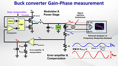
In power converters, the control loop plays an important role in the regulation characteristics of the converter. During the design stage it is important to check the stability of the control loop. Stability measurements are often done by measuring the control loop transfer function over a wide frequency range, and plotting the loop gain and phase versus frequency in a Bode Plot. |
 |
| Challenges of gain & phase measurements |
|
Loop gain and phase measurements can be tricky, because measured signals are small, and the injection signal can easily influence the normal behavior of the power converter. For measuring loop gain and phase, a network analyzer or frequency response analyzer is normally used, but these are complex and expensive items of equipment, and only show results in the frequency domain. |
| A better way to measure loop gain & phase |
|
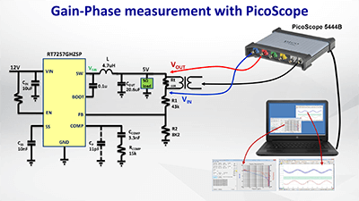
For accurate gain-phase measurement results, it is important to ensure the converter is working correctly during the gain-phase measurement. This can be accomplished by checking the converter signals in the time domain as well, under the same conditions as during the gain-phase measurement. A PicoScope® in combination with a Frequency Response Analyzer (FRA) utility can be used successfully for converter loop gain measurements, and it easily lets you check the signals in both time domain and frequency domain.
|
| An example of Buck Converter stability testing |
|
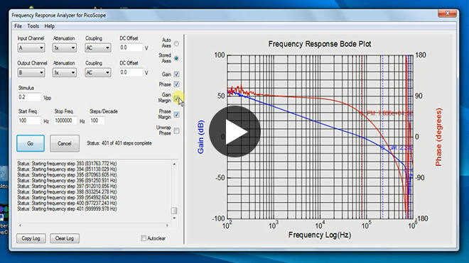
We have used a PicoScope 5444B with the FRA utility to measure the loop gain and phase of a popular Richtek current mode buck converter RT7257GHZSP in the 12V to 5V/2A application example which we explained in the previous EVB DIY video. We will use the PicoScope in Scope mode to check the loop input and output signals and converter switching, and then switch the PicoScope to FRA mode to measure the loop gain and phase at different operating conditions.
|
 |
|
FIND MORE PRACTICAL MEASUREMENT TIPS
IN THE VIDEO |
|
The tutorial video “How to measure Buck converter loop gain and phase” will explain the basics of control loop measurements and will show you how to use the PicoScope® with the FRA utility. We’ll also explain how to make the signal injection transformer that you need for this measurement. The video gives many practical tips and examples on converter stability measurement that can also be applied to many other converter types.
PicoScope is a registered trademark of Pico Technology.
|
|
NEW PRODUCTS
Check out the products that meet your area of interest for more information. |
 |
| RT7880 is a USB Type-C Power Delivery with integrated PWM Buck-Boost controller in a WQFN-40L 5x5 package. Delivering up to 100W, RT7880 is designed for charging mobile phones, tablets and notebook PCs in cars. It includes an embedded ARM Cortex™-M0 MCU for high flexibility, programmable cable drop compensation and protection features, VCONN support, customizable GPIO’s and master & slave I²C bus. |
| Find out more about RT7880 features
See other USB PD solutions
|
|
|
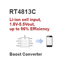 |
| RT4813C is a 1.8V-5.5Vin, up to 96% high efficiency Boost converter in a UQFN-9L 2x2 package. Featuring programmable 0.55A-3.1A limit and less than 1µA quiescent current, RT4813C allows systems to take advantage of new battery chemistries that can supply significant energy when the battery voltage is lower than the required voltage for system power ICs. |
| Get Free RT4813C Sample Now |
|
|
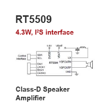 |
| RT5509 is a 4.3W output power, mono BTL class-D Speaker Amplifier with speaker protection in a WL-CSP-48B 3.04x2.99 package. Integrated a 2MHz, 1.5A Boost converter which provides programmable voltage up to 9.5V, RT5509 has I²S interface to support two different audio source with sampling rate up to 48kHz/24-bit. Its speaker protection provides mechanical/thermal protection with accuracy of 10%/±10℃ of rated limit. |
|
|
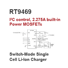 |
| RT9469 is a switch-mode single cell Li-Ion/Li-PolymerBattery Charger with USB-OTG for portable devices in a WL-CSP-25B 2.52x2.52 package. Featuring I²C control, the RT9469 integrates a 0.75/1.5MHz synchronous PWM controller, 2.275A power MOSFETs, input current sensing & regulation, and high accuracy voltage regulation and charge termination circuits.
|
|
|
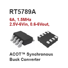 |
| RT5789A (PSM) is a 6A Iout, 2.5V-6Vin, 0.6V-6Vout, 1.5MHz ACOT Synchronous Step-Down Converter in a TSOT-23-8/ UDFN-8L 2.5x2 package. Featuring Power Good indicator and 1.5ms built-in Soft-Start, It is ideal for WLAN ASIC power/storage, handheld devices, STB, cable modem, xDSL platforms, etc. |
| Get Free RT5789A Sample Now
See other ACOT Buck converters
|
|
|
| |
|